The construction of a simple two-winding transformer consists of each winding being wound on a separate limb or core of the soft iron form which provides the necessary magnetic circuit.
This magnetic circuit, know more commonly as the “transformer core” is designed to provide a path for the magnetic field to flow around, which is necessary for induction of the voltage between the two windings.
However, this type of transformer construction were the two windings are wound on separate limbs is not very efficient since the primary and secondary windings are well separated from each other. This results in a low magnetic coupling between the two windings as well as large amounts of magnetic flux leakage from the transformer itself. But as well as this “O” shapes construction, there are different types of “transformer construction” and designs available which are used to overcome these inefficiencies producing a smaller more compact transformer.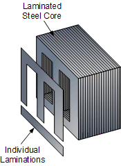
The efficiency of a simple transformer construction can be improved by bringing the two windings within close contact with each other thereby improving the magnetic coupling. Increasing and concentrating the magnetic circuit around the coils may improve the magnetic coupling between the two windings, but it also has the effect of increasing the magnetic losses of the transformer core.
As well as providing a low reluctance path for the magnetic field, the core is designed to prevent circulating electric currents within the iron core itself. Circulating currents, called “eddy currents”, cause heating and energy losses within the core decreasing the transformers efficiency.
These losses are due mainly to voltages induced in the iron circuit, which is constantly being subjected to the alternating magnetic fields setup by the external sinusoidal supply voltage. One way to reduce these unwanted power losses is to construct the transformer core from thin steel laminations.
In all types of transformer construction, the central iron core is constructed from of a highly permeable material made from thin silicon steel laminations assembled together to provide the required magnetic path with the minimum of losses. The resistivity of the steel sheet itself is high reducing the eddy current losses by making the laminations very thin.
These steel transformer laminations vary in thickness’s from between 0.25mm to 0.5mm and as steel is a conductor, the laminations are electrically insulated from each other by a very thin coating of insulating varnish or by the use of an oxide layer on the surface.
Transformer Construction of the Core
Generally, the name associated with the construction of a transformer is dependant upon how the primary and secondary windings are wound around the central laminated steel core. The two most common and basic designs of transformer construction are the Closed-core Transformer and the Shell-core Transformer.
In the “closed-core” type (core form) transformer, the primary and secondary windings are wound outside and surround the core ring. In the “shell type” (shell form) transformer, the primary and secondary windings pass inside the steel magnetic circuit (core) which forms a shell around the windings as shown below.
Transformer Core Construction
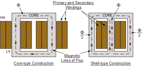
In both types of transformer core design, the magnetic flux linking the primary and secondary windings travels entirely within the core with no loss of magnetic flux through air. In the core type transformer construction, one half of each winding is wrapped around each leg (or limb) of the transformers magnetic circuit as shown above.
The coils are not arranged with the primary winding on one leg and the secondary on the other but instead half of the primary winding and half of the secondary winding are placed one over the other concentrically on each leg in order to increase magnetic coupling allowing practically all of the magnetic lines of force go through both the primary and secondary windings at the same time. However, with this type of transformer construction, a small percentage of the magnetic lines of force flow outside of the core, and this is called “leakage flux”.
Shell type transformer cores overcome this leakage flux as both the primary and secondary windings are wound on the same centre leg or limb which has twice the cross-sectional area of the two outer limbs. The advantage here is that the magnetic flux has two closed magnetic paths to flow around external to the coils on both left and right hand sides before returning back to the central coils.
This means that the magnetic flux circulating around the outer limbs of this type of transformer construction is equal to Φ/2. As the magnetic flux has a closed path around the coils, this has the advantage of decreasing core losses and increasing overall efficiency.
Transformer Laminations
But you may be wondering as to how the primary and secondary windings are wound around these laminated iron or steel cores for this types of transformer constructions. The coils are firstly wound on a former which has a cylindrical, rectangular or oval type cross section to suit the construction of the laminated core. In both the shell and core type transformer constructions, in order to mount the coil windings, the individual laminations are stamped or punched out from larger steel sheets and formed into strips of thin steel resembling the letters “E’s”, “L’s”, “U’s” and “I’s” as shown below.
Transformer Core Types
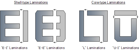
These lamination stampings when connected together form the required core shape. For example, two “E” stampings plus two end closing “I” stampings to give an E-I core forming one element of a standard shell-type transformer core. These individual laminations are tightly butted together during the transformers construction to reduce the reluctance of the air gap at the joints producing a highly saturated magnetic flux density.
Transformer core laminations are usually stacked alternately to each other to produce an overlapping joint with more lamination pairs being added to make up the correct core thickness. This alternate stacking of the laminations also gives the transformer the advantage of reduced flux leakage and iron losses. E-I core laminated transformer construction is mostly used in isolation transformers, step-up and step-down transformers as well as auto transformers.